Sensors & Usage
Overview
The sensor setup is illustrated in Fig. 1. The corresponding ROS topics are reported in Tab. 1.
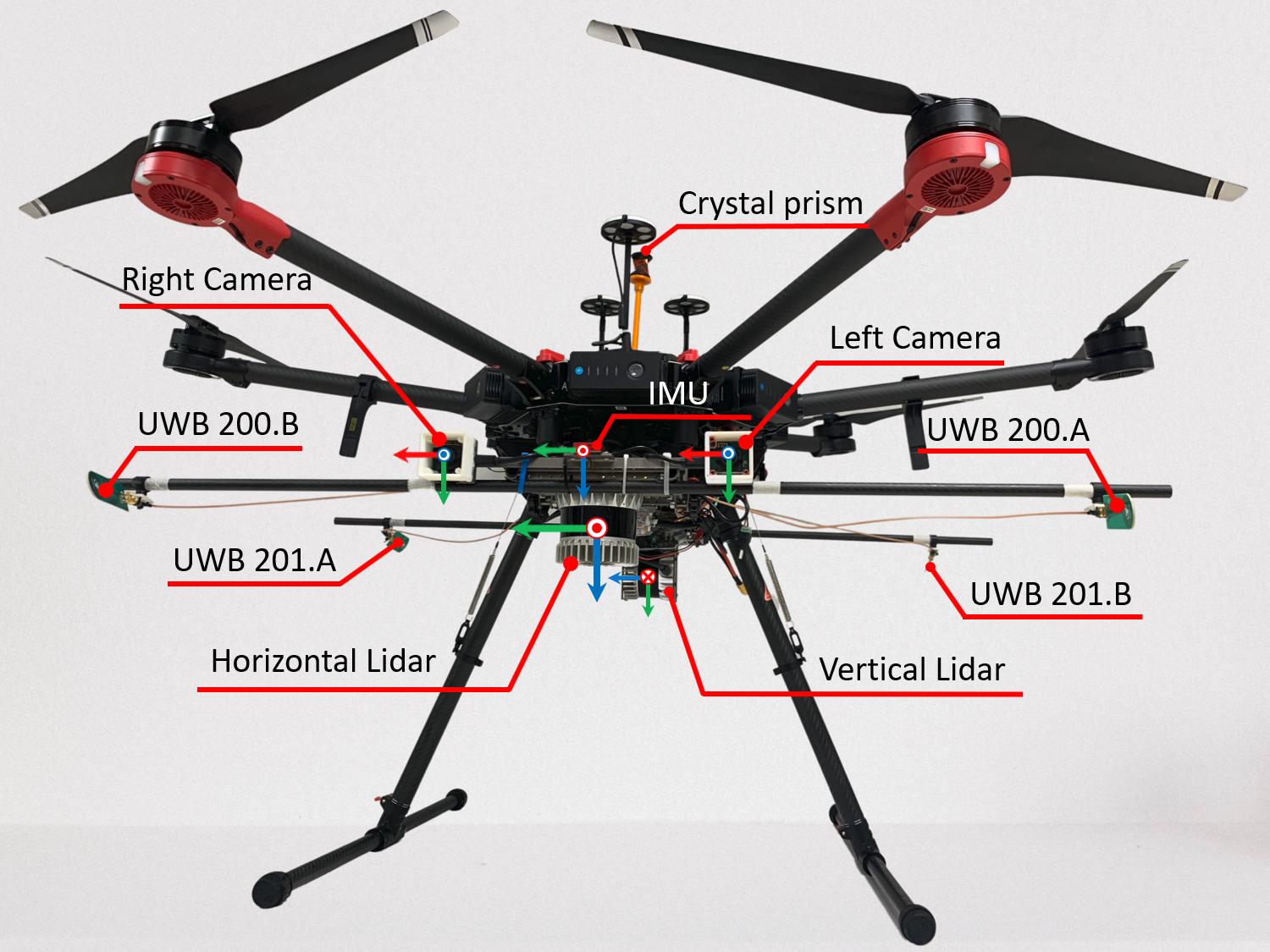
Fig 1. The research UAV with its sensors and corresponding coordinate frames
Table 1. Sensors and their ROS topics
| No. | Sensor | Manufacturer & Product name | ROS topic name | Message Type | Nominal Rate |
|---|---|---|---|---|---|
| 1 | IMU | VectorNav VN100 | /imu/imu | sensor_msgs/Imu | 385 Hz |
| /imu/magnetic_field | sensor_msgs/MagneticField | 385 Hz | |||
| /imu/temperature | sensor_msgs/Temperature | 385 Hz | |||
| 2 | Horizontal Lidar | Ouster OS1-16 gen 1 | /os1_cloud_node1/imu | sensor_msgs/Imu | 100 Hz |
| /os1_cloud_node1/points | sensor_msgs/PointCloud2 | 10 Hz | |||
| 3 | Vertical Lidar | Ouster OS1-16 gen 1 | /os1_cloud_node2/imu | sensor_msgs/Imu | 100 Hz |
| /os1_cloud_node2/points | sensor_msgs/PointCloud2 | 10 Hz | |||
| 4 | Camera 1 | uEye 1221 LE (monochome) | /left/image_raw | sensor_msgs/Image | 10 Hz |
| 5 | Camera 2 | uEye 1221 LE (monochome) | /right/image_raw | sensor_msgs/Image | 10 Hz |
| 6 | UWB | Humatic P440 | /uwb_endorange_info | uwb_driver/UwbRange | 68.571 Hz |
| /uwb_exorange_info | uwb_driver/UwbEcho | 5.714 Hz | |||
| /node_pos_sc | nav_msgs/Path | 5.714 Hz | |||
| 7 | 3D Laser Tracker | Leica MS60 TotalStation | /leica/pose/relative | geometry_msgs/PoseStamped | 20 Hz |
IMU
The IMU being used here is a 9-DoF inertia sensor. The frame of reference attached to this sensor is considered the body frame of the whole setup.
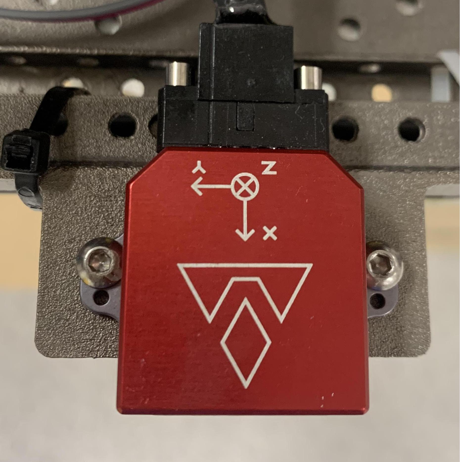
Fig 2. The IMU frame of reference
Internally, a filter fuses gyroscope, acceleration, and magnetic field measurements and outputs the orientation result on the /imu/imu topic. Though our dataset does not have orientation groundtruth, user can consider this orientation estimate as one.
Cameras
The two cameras are externally triggered to capture images at the same time. For images triggered at the same time, their time stamps are different by at most 3 ms. This satisfies the default hardcoded threshold in VINS-Fusion. See our tutorial on how to run VINS-Fusion with the dataset here.
Lidar
The Lidar model used for this dataset is OS1-16 gen 1 from Ouster. Each message under the topic /os1_cloud_node1/points or /os1_cloud_node2/points corresponds to a full 360° scan, which can be converted to a pointcloud of resolution 16x1014. Notice that besides the common x, y, z, intensity fields, each point in the pointcloud also contains time, reflectivity, ring, noise, range information of the laser firing. To fully access these information, add the following definition of the Ouster point type to your code:
struct PointXYZIRT
{
    PCL_ADD_POINT4D;
    float intensity;
    uint32_t t;
    uint16_t reflectivity;
    uint8_t  ring;          // The channel index
    uint16_t noise;
    uint32_t range;         // The distance measurement
    EIGEN_MAKE_ALIGNED_OPERATOR_NEW
} EIGEN_ALIGN16;

POINT_CLOUD_REGISTER_POINT_STRUCT(PointXYZIRT,
                                  (float, x, x)
                                  (float, y, y)
                                  (float, z, z)
                                  (float, intensity, intensity)
                                  (uint32_t, t, t)
                                  (uint16_t, reflectivity, reflectivity)
                                  (uint8_t,  ring, ring)
                                  (uint16_t, noise, noise)
                                  (uint32_t, range, range))
Below is an example callback that converts the ros message sensor_msgs/PointCloud2 to an object of type pcl::Pointcloud<PointXYZIRT> defined above:
// Global variable to store the cloud data
pcl::PointCloud<PointXYZIRT>::Ptr laserCloudIn;

// Callback of topic /os1_cloud_node1/points
void cloudHandler(const sensor_msgs::PointCloud2::ConstPtr &msg)
{
    laserCloudIn->clear();
    pcl::fromROSMsg(*msg, *laserCloudIn);
}

// Subscribe to /os1_cloud_node1/points and allocate memory for the pointcloud somewhere in the main function
// Example: laserCloudIn = pcl::PointCloud<PointXYZIRT>::Ptr(new pcl::PointCloud<PointXYZIRT>());
UWB
The UWB sensors used in this work are the P440 UWB Ranging and Communication sensor by Humatics. We converted the driver's custom message types to ROS messages, with some additional fields. The definitions can be found in the following package. You can simply git clone the package to your workspace and do catkin_make. The following headers can be included in your code
#include "uwb_driver/UwbRange.h"
#include "uwb_driver/UwbEcho.h"
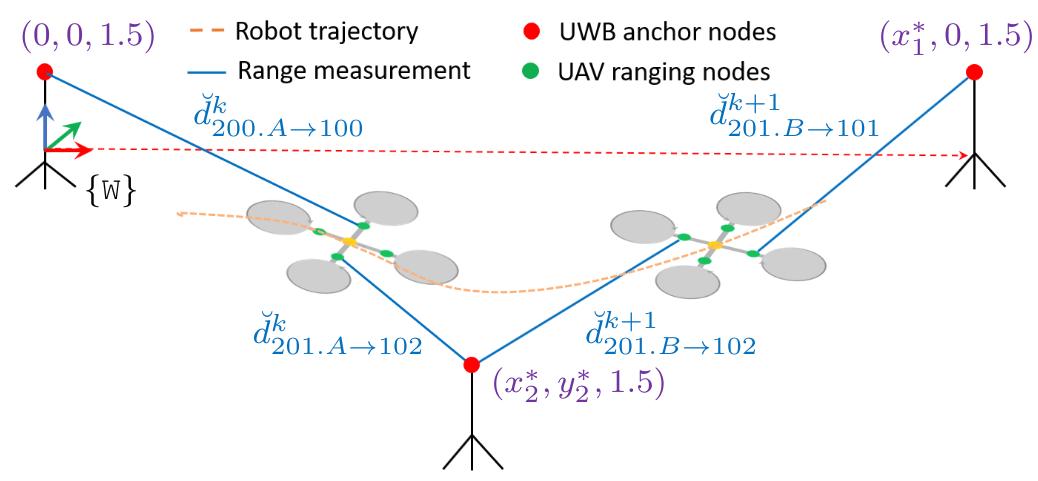
Fig 3. Illustration of the ranging scheme
Fig. 3 illustrates our ranging scheme with 4 onboard UWB ranging nodes 200.A, 200.B, 201.A, 201.B, called requesters; and 3 anchor nodes with ID number 100, 101, 102, called responders. Each range measurement contains the IDs of both requester ID and the responder ID. By our subjective design in Fig. 3 above, the three anchor nodes create a coordinate frame of referece {W}, where the anchor 100 is 1.5 m above the origin, the anchor 100 is 1.5 m above the +x axis, and anchor 101 is at the same height and on the -y side of the space.
Let us take the example of the distance measurement from the onboard node 201.A and the anchor 101 (in the absence of noise) as follows
In this case is the position of the UAV's body center,
is its orientation,
is the position of the requester node in the body frame, and
is the position of the responder node in the user-defined frame {W}.
In a typical navigation system, and
will be the unknown quantities that one needs to estimate, while
and
are priors that can be retrieved from the
uwb_driver::UwbRange message. Fig. 4 shows where these priors can be obtained in a message under the topic /uwb_endorange_info.

Fig 4. The content of a range message
Note that the anchor positions are calculated by simple triangulation of anchor-to-anchor distance under the topic /uwb_exorange_info at the beginning of the data collection test. User can opt to estimating these on their own by subscribing to the topic /uwb_exorange_info.